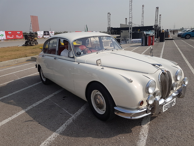
Battery Charging System: It’s been about one and a half year since I posed here. Mainly, because the car was used very sparingly and the few times it was used, it performed flawlessly until a few weeks ago. About three weeks ago, I needed to attend a meeting; all our other cars were unavailable so I had no other choice but to take this one.
About a kilometre into the journey, I noticed the ammeter was erratic, flicking violently from +15 to -15 amps accompanied with erratic flashing of the ignition charge light. All these were indications that the charging system was not well.
As I was pretty close to my house, I just turned around and limped back home and took Careem to the meeting. Upon my return I had a look under the bonnet to investigate. Visually nothing was wrong. Belt, wiring etc. all looked pretty OK.
I opened the voltage regulator box cover to see if the regulator contact were dirty or burnt. Contacts looked fine. I cleaned them just as one cleans CB points, ran the engine but no change. However I saw the regulator points opening and closing erratically just as the ammeter needle was swinging violently. Under normal circumstances, these points are supposed to be open at idle and close at fast idle. Closing of these points allows the dynamo current to flow to the battery.
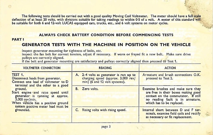
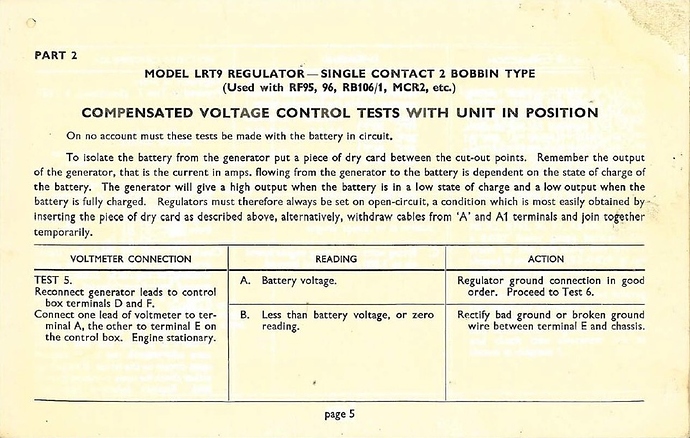
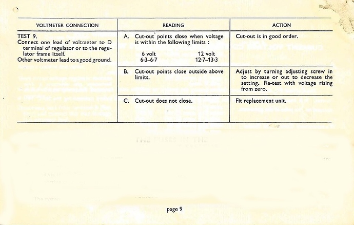
Next was to read up on the system to educate myself about it so that I could trouble shoot. The Lucas dynamo/charging system has a specific test procedure comprising of 4 steps and the voltage regulator has a 6 step test. As a matter of interest, I will present the relevant pages of the Lucas booklet here:
Dynamo Test Procedure as mentioned in the Lucas booklet:
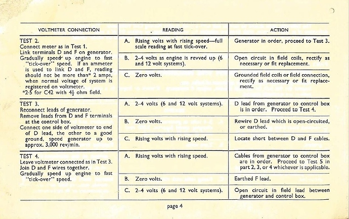
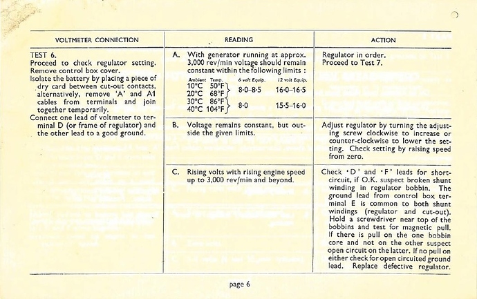
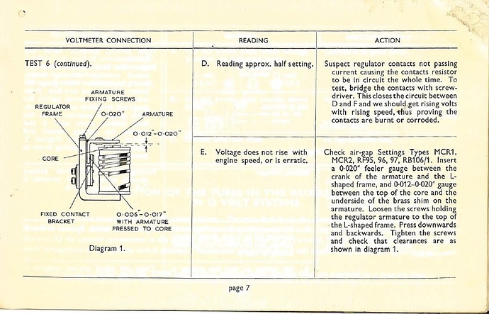
Regulator in-situ Test Procedure from same Lucas booklet:
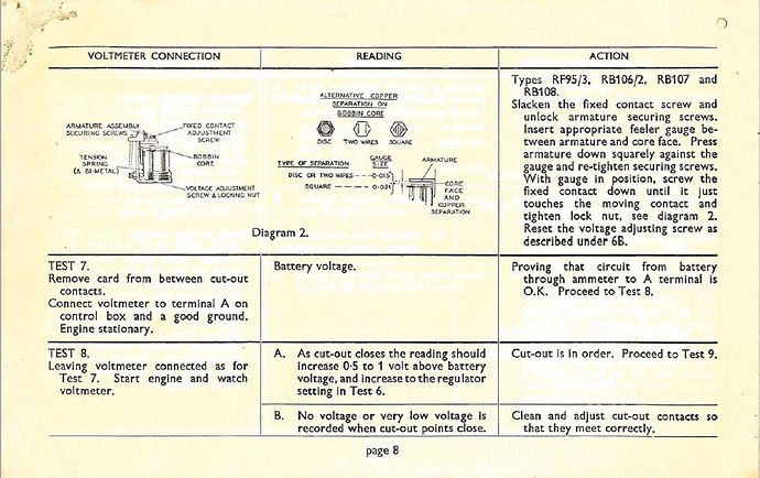
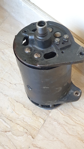
Dynamo: Logical place to begin was where the electricity is made - the dynamo. There are two wires at the dynamo, three, if you count the earth strap. One wire is marked ‘D’ and the other marked ‘F’. The ‘D’ is the Dynamo main connection and the ‘F’ is the dynamo field connection. First test was to disconnect wires ‘D’ and ‘F’ and measure the voltage at the dynamo. I used a digital multi meter for these tests. The wires ‘D’ and ‘F’ wires were removed from the dynamo were taped up in case they touch the body during the testing process. Voltage across ‘D’ and Earth was measured to be 1.9 to 3 Volts. I noticed that the reading were not steady. Digital voltmeters do not react fast enough to follow voltage fluctuations – analogue meter would have told a different story. Next test was to short out terminals ‘D’ and ‘F’ and check voltage across this short and earth. This test revealed a voltage of 24V at fast idle. Again the reading was not steady. Though these reading were in line with the Lucas tests, but the non-steady readings lead me to investigate the dynamo further. Belt was removed and dynamo turned by hand.
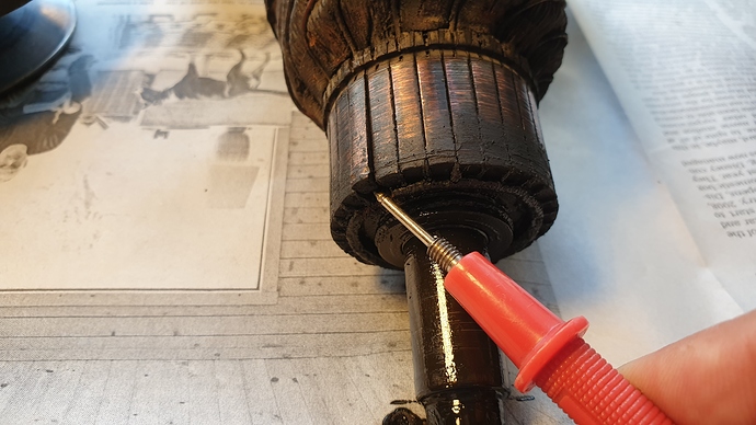
Upon turning the dynamo by hand I heard a clicking noise from within the device. There is a cover over the carbon brushes, I removed said cover to see inside or rather feel the commutator as I turned the dynamo by hand. I felt one of the commutator elements had lifted. With this finding, could it be that this lifted element was causing the carbon brushes to jump as it passed under them. Each of these jumps caused a stoppage of dynamo output, making the dynamo output to be unsteady causing the ammeter to flick between charge and discharge?
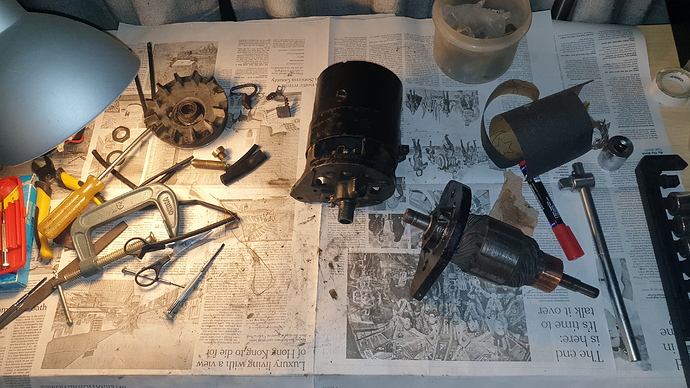
Out came the dynamo for a strip down
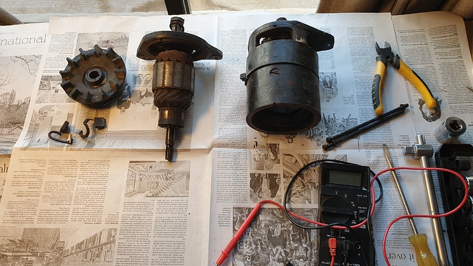
Almost all the components of the dynamo laid out
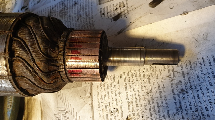
The offending commutator element
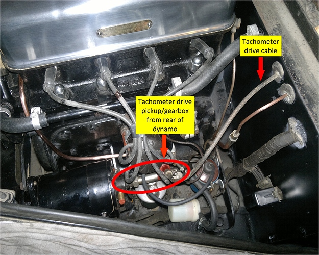
If this was 1948 or 1950, I would have gone to Polad and Co. in Karachi and simply ordered a new armature. But this is not 1950 and M/s Polad are not the Jaguar agents in Pakistan anymore. To make things a bit more interesting, this particular armature is not the usual run of the mill Lucas C45V armature. It is in fact a C45YV which has a special extension of armature shaft that drives the RPM meter cable. So any alteration will render the RPM meter non operational. Long story short, I have to repair this commutator. Further checking of other elements revealed that though they had not lifted, but they were loose.
Elements marked in red are loose but not lifted.
A trip to the forums of various English cars revealed that others with the same problem have used Araldite to re-fix their commutator element(s). From the factory the elements are moulded in a fiber/Bakelite type material and are not strictly repairable. But here I have my back to the wall. Repair was done with clear epoxy rather than steel epoxy due to electrical conductivity issues.
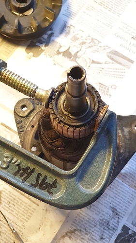
Light pressure applied as I waited for epoxy to dry.
When wife saw this mess, she thought I had gone mad.
After it set, next was to check the trueness of the commutator. If all the elements (28 in all) are not flat, the brushes will wear out very fast. The newly fixed element did not sit totally flush with its neighbours. A bit of judicial filing and sand papering was done to address this issue. In another world, I would have had the commutator trued on a lath machine, but I think it is too old and delicate to sustain the force of the lath machine tool.
After I was quite satisfied with the repair, I refitted the dynamo and connected it up. Stationary test run of the charging system revealed that the ammeter now showed the system charged (15 Amps) until about 2000 RPM and then, as if a switch was thrown, jumped to discharge of 15 Amps. A very disappointing result indeed. This was a bit of a disaster and I was at a very low place at this moment. The problem remained but the behavior of the system had changed.
Regulator-Cut out: The only other device that could be at fault would be the regulator-cut out. Back I went on the internet to read up about how it functioned. Also I have another Lucas booklet that explains in much details of how this device works. I will take you along on this journey.
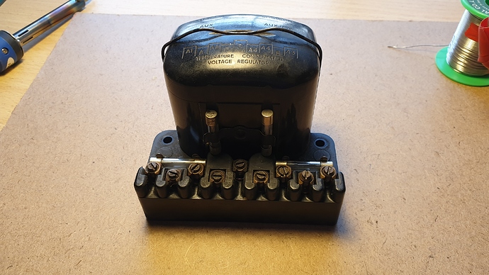
Regulator/cut out removed from the car
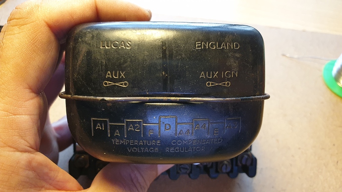
Terminal identifications – 9 in all. Hence this is called a 9 post Regulator. Model number is RF95/2
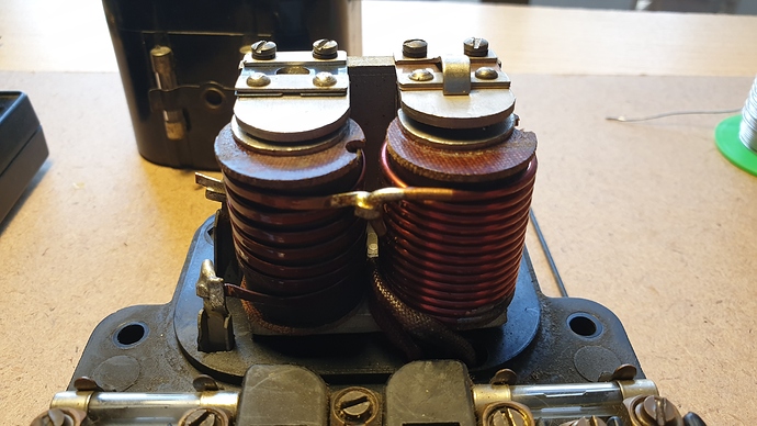
Cover removed. Coil on the left is Regulator and the other is the Cut out.
We begin with the schematic, though, it looks a bit complicated but it can be broken down to a simpler components.
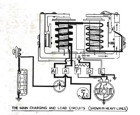
Regulator/Cut out schematic
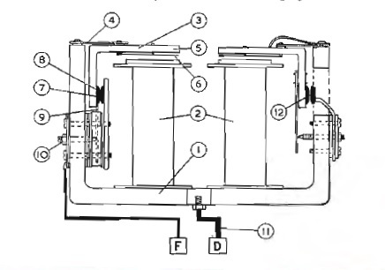
Schematic components
General description: There are two coils (2) mounted on a common yoke (1). The one on the left is the regulator and the one on the right is the cut out. Both these are electromagnet coils that open and close a set of points each (7 & 12). So basically they are relays with the additional feature of being able to adjust the gap of the points. Altering the gap alters the charge control of the system. The points (7) of the regulator are normally closed and the points (12) of the cut out are normally open. Both coils receive their excitation current from the terminal ‘D’ (11) which as mentioned earlier is the dynamo main wire.
Below are schematics of the connections of the excitation coils of the Regulator and Cut out:
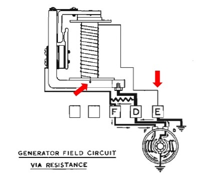
The Regulator coil showing the excitation winding. One end of this coil is connected to Earth and the other to terminal D via the yolk. The resistance between F and D is provided to prevent arcing as these points open and close at a frequency of up to 100 times a second.
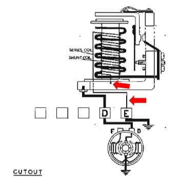
Ignore the thick coil. The thin coil is the excitation coil and it too is connected with one end to the yolk and the other to the earth.
Hence both these coils are connected in parallel to the dynamo. So if I was to test the coils for continuity or short, I would have to separate them and test them individually. Separating them involves unsoldering the coil connections at the ‘E’ terminal. Once separated, I could individually apply 13.5V to each excitation coil and see if the armature (3) was being draw by the magnetic action of the coil. I was able to determine that the Regulator coil was not able to magnetize while the Cut out coil was totally healthy. This brings me to say that the Regulator is toast.
Now this brings me to the point of looking for a replacement Regulator/cut out device. Searching the net has delivered three options:
1 – Replacement RF95 regulator made in India. Internally has the same two coils and points etc. (sold through UK stores): GBP 129/-
2 – Same as above but made in UK: GBP 129/-
(I think they are not telling the truth, this one is also made in India – there are some telltale signs that make me say so).
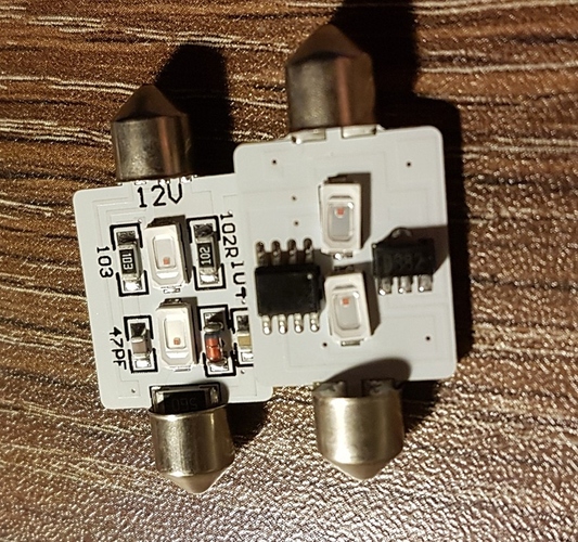
3 – Replacement RF95 regulator that has no moving parts i.e. solid state item with up to date modern internals. Externally looks just like my original item. GBP 145/-
Though (3) is more expensive but I am inclined to go with this one. The idea being that hopefully this will last more than 70 years