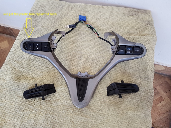
Steering audio controls project started by myself as DIY ...
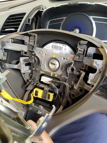
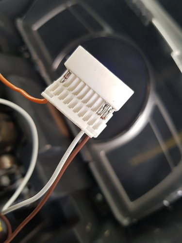
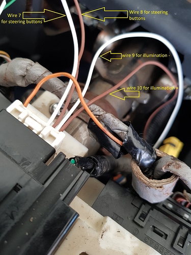
OK here we go.I'm not going to go into detail about how to take apart the dash.There is a great description with pictures found in our great zunny bhai's thread HERE.ive took all the help from this thread and some help from international forums as well because the japanese steering controls which ive got comes with blue grip and have different slots (7 and 8) for audio controls allotted in its clockspring (as comapred to zunny bhai steering controls 4 and 5) but illumination wiring slots ( 9 and 10) were same ..
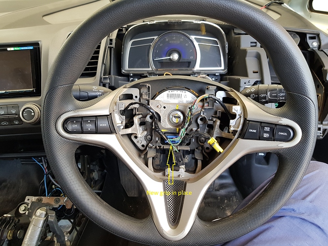
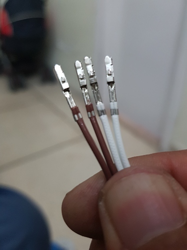
Those new wiring pins exactly like OEM can be really hard to find but ive found them attached with some extra wires lying inside my headlight projectors boxes and after that you have to push them into the new slots which may require the help of a screw driver pushing them to get them all the way in.Notice that they should only go in one way, make sure to install them the right side up and never let them touch each other otherwise some fuse will be blown somewhere inside the dash (in my case 7.5amps fuse no 14 was blown inside dash) ..
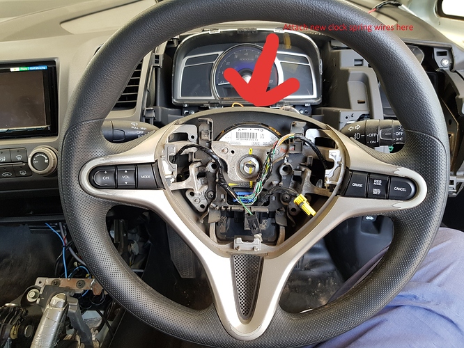
Wiring Connections
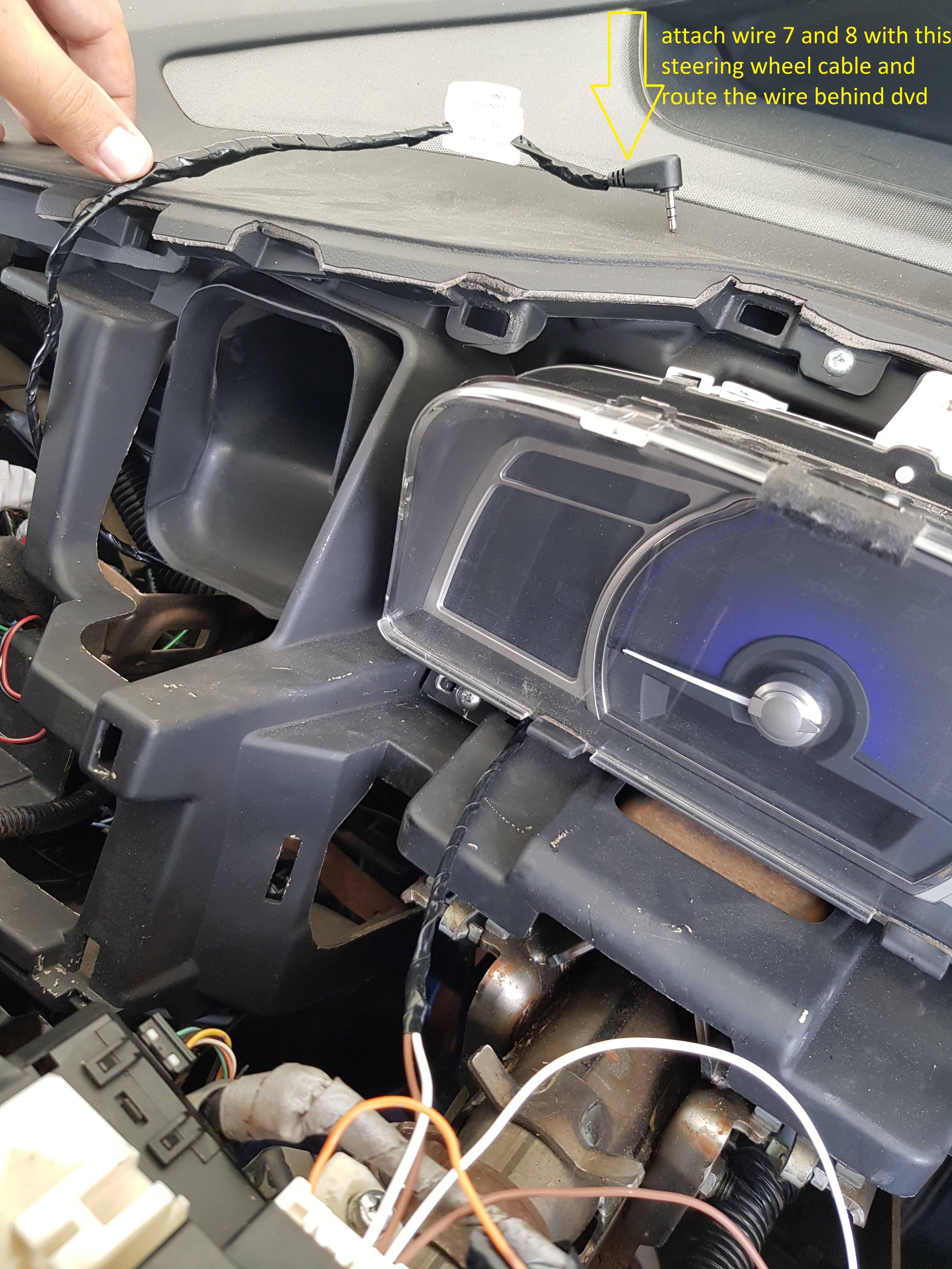
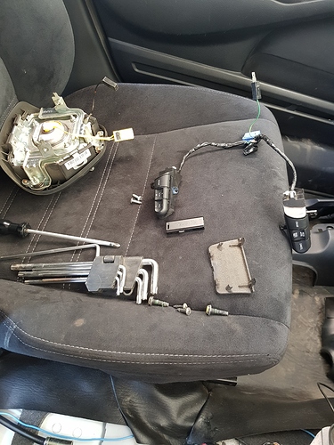
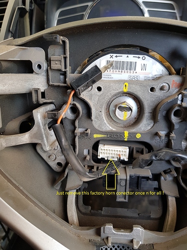
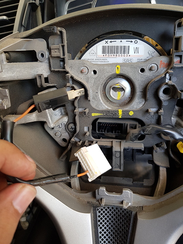
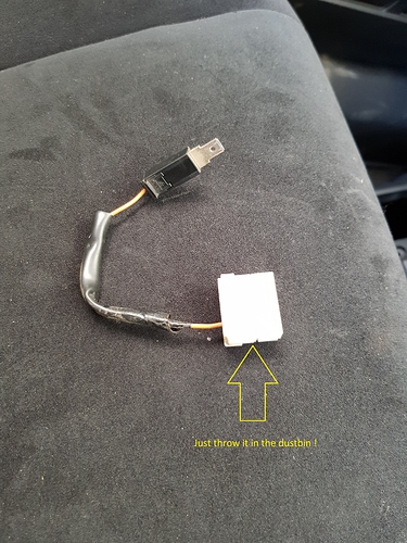
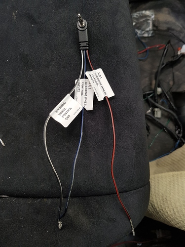
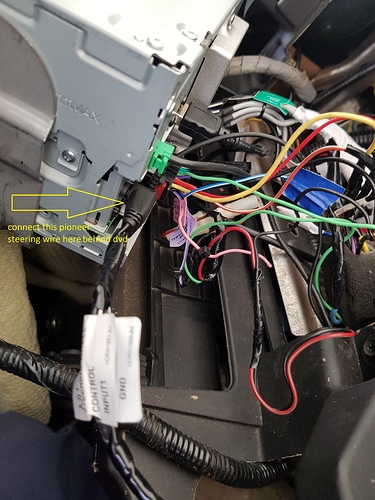
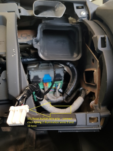
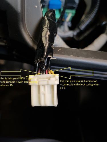
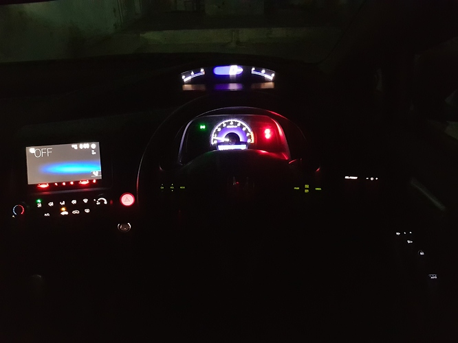
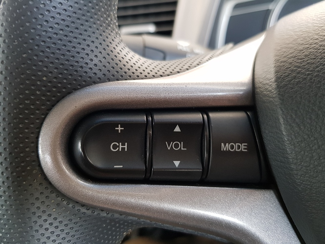
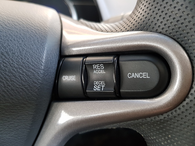
if you got an oriel dont even need to remove whole steering wheel just remove airbag only .. plus you need just steering buttons and 4 new wires and thats about it .. (2 wires for steering buttons and 2 wires for illuminating these buttons) .. put all these 4 new wires in clock spring slot no 7 , 8 , 9 and 10 .. so once all clock spring connections are made it gets really easy to connect it to dvd side ive connected it with my aftermarket pioneer dvd ( most of these aftermarket pioneer dvds comes with a separate wire for activating steering controls) .this wire has pin at one end and 3 wires on the other side with labels steering wheel control input 1 , steering wheel control input 2 and steering wheel control Gnd) .. ive just connected steering wheel control input 1 wire with clock spring at slot no 7 then ive joined both steering wheel control input 2 and steering wheel gnd wire together and connected them with clock spring slot 8 wire .. after that go inside dvd menu for steering buttons calibration ! now attach 2 remaining wires at clock spring slot 9 and 10 (slot 9 is illumination negative and slot 10 is illumination positive) with sel/reset buttons wiring grip (pink thin wire for illumination negative and grey thin wire for illumination positive) and its done now on to some pics